The flooding of Kuma Creek has caused massive destruction to properties and confirmed six fatalities downstream. Kuma Creek is such a small creek which is a tributary of Gumanch River which joins with other rivers to form the Wagi River in the Western Highlands Province.
It is unbelievable for such a small creek to cause massive destruction to lives of people and properties downstream. According to preliminary report posted on Facebook dated 4th February 2020 by Stanley Kheel Kewa, it reads:
"Preliminary reports from Mt Hagen confirm massive scale of destruction by the Kuma river a tributary of the Gumanch river in Mul district of Western Highlands Province. Four adults and five children totaling nine casualties as reported deaths now. More investigations are in progress as surrounding communities are assessing and investigating the magnitude of the destruction.
Local tribes in the area are the Nengka, Munjika & Mele tribes. Locals reporting from Hagen say this is one of the worst natural disasters the community has ever experienced since time immemorial. The Kuma & Gumanch rivers originate from the top peak of the highest mountain range in WHP known as the Mt Hagen range from which the current Hagen city got its name.
The Nengka Kuiprungils, Nengka Oiyambs and Munjika Rapgangils live at the edge of the Hagen range with houses and gardens patched along the Gumanch and Kuma tributaries.
Ken Paul is a local from the area and reports he is in Hagen town trying to mobilize disaster office and news personnel into the area for further investigations and reporting.
This is just a preliminary report with photos of the disaster zone downloaded from fb pages."
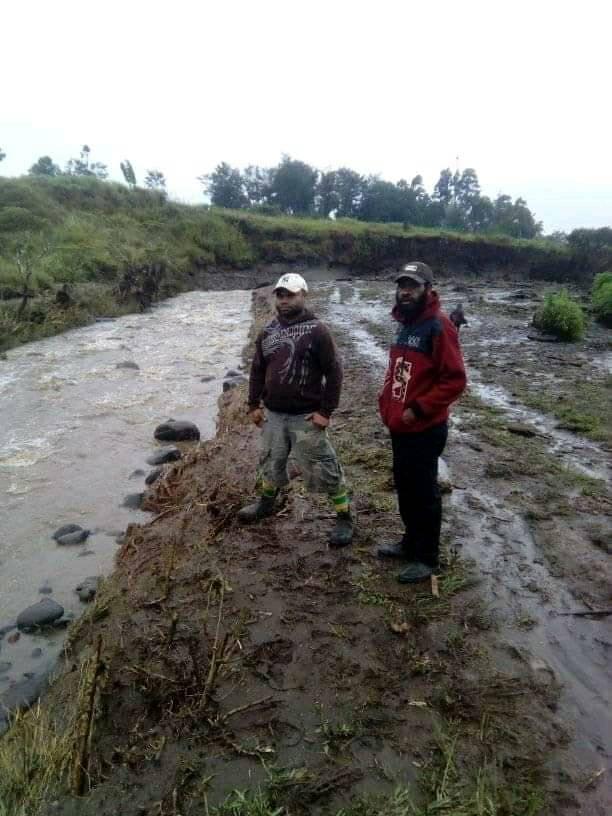 |
| Locals on site - photo courtesy of Facebook |
 |
| Photo Courtesy of The National Newspaper |
 | ||
| MarapanaVillage aftermath - photo by National newspaper |

Now,
one would wonder with questions in anticipating superstitions without establishing the facts and without even having a curiosity in mind. The possible cause of the flood can be best explained as follows;
There must be couple of landslips
caused by what is believed to be over saturated water-table/reservoir
contain by permeable rocks
at both steep
sides of the wedge walls/hills
of Kuma Creek which is indicated on the snapshot below.
Then the slipped materials must have
formed an embankment or base which blocked the upstream and the water built up at the upper end of the embankment which formed a temporary mini dam.
As the mini dam rose with altitude, the stress build up also increased until it reached a
bursting failure in which debris of embankment together with other slipped materials along the creek's
pathway were all washed away and flooded the banks of Kuma and Gumanch Rivers which caused the catastrophic destruction to properties and fatality of 6 human lives.
The mass flow of loose materials which blocked the flowing river which resulted in forming a mini dam were not competent or strong enough to withstand the pressure/stress build up at the upper end of the blockage, it then burst out and flooded the downstream at a greater momentum which is possible for massive destruction.
 |
| Expected failed area |
 |
| Location Failure is Expected |
Note that this analysis is based on opinion only and not substantiated with facts. If someone wants to proof with factual information then someone need to take a walk up the Kuma river and look for any trace of landslip. If that is so then that would be the cause of the flooding.
To prevent properties and lives, build houses on higher grounds and also build flood walls along the river banks where valuable properties are installed. Do make awareness to kids and matured people to evacuate quick if unexpected signals are given before massive destruction happens again.
|