


Geothermal
System Modelling
Report Submitted
by Group Fuji
Basic Model
1.0 IntroductionThe Basic Model parameters (basicmodel.in) was used to calculate the transient behaviour of the hydrotherm system up to 100,000 years. Team Fuji analysed the calculation results in the numerical model by changing one of the parameters in the initial model and run the simulation using HYDOTHERM. In this case, the team changed the size of the heat source while keeping the other parameters constant in the model. The calculation results were run at 20000,40000,60000,80000 and 100000 years.
 |
| Fig. 1 Heat source at the deeper layer of the model (2km thick) |
 |
| Fig. 2 Section View of the initial model |
 |
| Fig. 3 Overview of the initial block model |
 |
| Fig. 4 Section view of the block model when heat source decreased to 3km x 3km |
 |
| Fig. 5 Sectional view of the block model when increasing
the size of the heat source by 6km x 6km |
Note:
everything else is kept constant except the size of heat source changed for the
next two models.
2.0 Discussion
1.1 Heat source
The trend of the cooling equations (below) illustrate the differences in the thickness of the heat sources. Therefore, the larger the areal extent of the heat source is inverse proportional to the cooling rate. The bigger the heat source, the longer it takes to for it to cool down.
 |
| Figure 6: Cooling rate of the heat source |
The cooling equations for the model with 3kmx3kmx2km,
4kmx4kmx2km and 6kmx6kmx2km heat sources are shown below:

1.2 Rate of cooling of the reservoir
The
graph below portrays the cooling rate of the reservoir, approximately 1km above
the heat source where the convective heat transfer currents are mostly
upwelling.
|
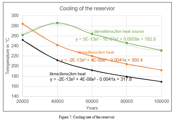 |
| Figure 7: Cooling rate of the reservoir |
The
reservoir cooling curves in Fig.7 above have near - similar trend except for
the model with 6kmx6kmx2km heat source which has a kink upwelling at 40,000
years.
1.3 Interstitial steam and water flow
1.3.1 3kmx3kmx2km heat source model
At
20,000years, the hot water rises from the center of the model and travels
upward towards the surface as interstitial water moves slowly to recharge the
reservoir. At 40,000 years, the rising hot water together with the conduction
heat transfer heats a larger area above the magma thus expanding the reservoir
area (region in which hot water rises upward).
From 60,000 to 100,000 years, the model cools to below 200°C and
convective currents carrying hot water upward weakens over time.
 |
| Figure 8: Simulation of 3km x 3km x 2km heat source after 20000 years. |
1.3.2
6kmx6kmx2km heat source model
At
20,000years, we have two convective upflow regions which may form two
reservoirs about 1km on either side of the center of the model (approx. 9000m
and 11000m from LHS of the model).

At 40,000yrs, the two
reservoirs merge into one as the heat source cools with convective currents weakening
as the model ages all the way to 100,000years.
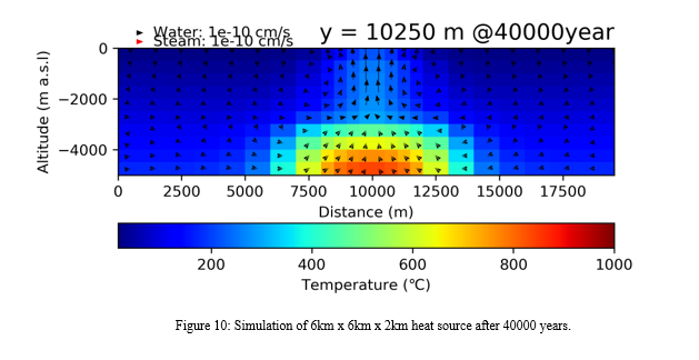 |
| Figure 10: Simulation of 6km x 6km x 2km heat source after 40000 years. |
3.0 Conclusion
In
this study, only the heat source dimensions were varied without any change in
other parameters. The results were then
evaluated and discussed using that assumption.
The
areal extent of the heat sources directly influences the convective flow of
fluids and temperature. However, transient temperature evaluation indicates
that the rate of cooling of the heat source is inversely proportional to the
size of the heat source. The larger size (6km x 6km x 2km) of the heat source allows
for a longer period of high-temperature fluid convection.
 |
Figure 12 : 3X3 Heat source Figure 11: 6X6 Heat source
|
Source: Groupwork Hydrotherm Basic Model Assignment Report -
Contributions to Group Fuji:
Islomove Sunnatullo-Rock Engineering, Koskey Philemon Kiprotich- Geothermics, Gilbert Bett Kipngetich-Geothermics, Gutierrez Donaire Kevin Yamil - Geothermics, Haissama Osmanali - Geothermics, Kuri Las - Rock Engineering, Lim Pagna-Economic Geology, Mwangi Samuel Muraguri -Geothermics, Ngethe John-Energy Resources, Omondi Philip Omollo-Geothermics, Samod Yuossouf Hassan - Economic Geology


0 comments:
Post a Comment