General information of Coal Gasification
Underground coal gasification is a concept of extracting underground coal by burning it underground extracting the bi-products for usage. there are different techniques which are published by various researchers around the globe that you can search for.
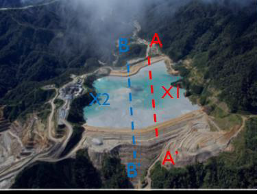
Some researchers continue to explore how to extract useful gases by burning coal underground. Below is an experimental setup in a laboratory observed by Kyushu University Students.
Activities - Daily Account
of experiment
In this project of the Underground coal gasification
simulation, it was done in a laboratory setting to analyze the potential of underground
coal gasification for potential utilization of underground coal resources.
 |
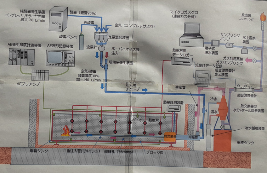
| Figure 1 : Schematic diagram of the coal gasification model at laboratory setting |
The purpose of this project was to simulate the coal ignition
to extract the Hydrogen and Carbon Dioxide gas and other important gases. Other uses of in-situ coal by coal gasification include the
production of electricity, coal tar among others but in this case the coal tar
is of insignificant and considered as waste with water.
The account of the activities conducted during the experiment are outlined below.
Day 1
Set up the experiment
especially connecting the sensor cables from the coal seam model to the sensor
measuring equipment. Two (2) drill holes were created and installed cracking
sensors and cemented. crack sensor cables were channeled to detect crack
location while burning. The closest crack returns the highest reading.
All the
sensor cables were connected to the sensor reading equipment and calibrated
based on calibration standards and trial/tests done to ensure all good to go. The
sensors were to measure temperature, cracking of coal, flow rate of gas
emitting under atmospheric pressure.
Oxygen was prepared to connect into
the model so that it will aid burning coal under enclosed setting and help in
getting out the resultant gas/products from the coal burning face. LP gas was also used with a long copper tube
and a ignition coil attached at the end of it for igniting the coal. All other necessary pipes were connected and
ready for experiment.
All the set up was done and ready for
ignition on the next day.
 |
| Figure 2 : Equipment set up completed and ready for measurement during coal burning |
Day 2
Ignition of coal started in the morning by burning
the ignition coil attached to the copper tube with electricity which is
connected to the LP gas. When the ignition coil was red hot, LP gas was opened,
and it flowed through the copper tube and flame burst. This set up was
inserted into the coal seam and the coal seam was ignited in the model.
As the coal seam was burning in the model and
producing smoke, the ignition coil setup removed, and oxygen was supplied into
the enclosed area to aid burning and closed the inlet/outlet pipe or the
regulator pipe. Oxygen also help in getting the resultant gas and moisture out
from the burning face.
Electric buster fan was used to suck smoke away from
the working area. At the regulator pipe, the emitted gas during the burning of
the coal is collected via metal pipe and monitored and recorded at the laptop
inside the laboratory. Excessive gas emitted at two exit pipes above the
building was then lighted up by gas burner to continue burning to prevent smoke.
After some time, water is connected
into the burning area via pipe to prevent excessive burning and protect non
coal components of the model.
The gas produced from burning coal is
a mixture of gas and moisture so there was a mixing chamber or collecting tank
which was wrapped with clear hose and frozen
water pumped through and the moisture content got condense which also contain
coal tar and is collected at the bottom/tip of the storage tank and further
stored away in storage containers for disposal.
Readings of the temperature, flowrate,
cracking are recorded hourly on prepared data sheet. Readings were also
recorded continuously on the equipment and data is stored in memory disks. The
recording of data is done hourly and 24 hours for 4 days.
 |
| Figure 3 : Water and coal tar mixture collected at the condenser tank |
Day 3
The hourly recording of temperature, cracking
and flowrate under atmospheric condition continued.
The laboratory demonstrated and explained in simple
terms the experiments to Junior High School Students. There were three set up on site at the research facility
for students to observe:
1.
(a)The explanation of coal and demonstration
of how coal and rock in terms of their physical properties.
(b)
The coal and gravels were burned, and the results showed that gravels cannot
burn but coal can burn when ignited.
(c) Another
set up was that, coal was placed in a glass tube closed at the opening and a
small L tube is connected. Using gas burner, the glass tube containing coal was
burned and gas was produced and emitted through the L tube and finally lighted
by gas lighter and it was burning and students were amazed with this experiment.
 |
| Figure 4 : Burning coal in the glass tube as a demonstration of coal gasification |
2. Explanation
and demonstration of electricity generation by burning coal. Glass beaker was
filled with water and firmly closed, and a tube connected via lid. This tube is
then connected to a mini turbine with motor attached at the end and wiring was
done to produce electricity and a light was produced. By using gas burner, the beaker with water
was heated and high pressure steam produced which is directed via the tube and
into the turbine which turns the turbine and as the turbine rotates, it powers
the motor which converts the mechanical energy to electrical energy.
 |
| Figure 5 : Demonstration of steam turning the turbine to power the motor and a red light given out. |
3. The
third set up was the explanation of the setting up of the underground coal gasification
process and procedures and the explanation of the model being set up.
 |
| Figure 6 : Schematic Diagram used to explain the coal gasification set up at laboratory. |
Day 4
The hourly recording of temperature,
cracking and flowrate under atmospheric condition continued and Hosted the another
group of Junior High School Students and conducted the same experiments and
explanation on the previous day .
 |
| Figure 7 : Junior High School Student and technical team on site after completion of explanations. |
Day 5
Continued with hourly recording of
temperature, cracking and flowrate under atmospheric condition and removing wastewater
from tank and poured into storage containers for treatment before disposal.
Day 6
Recording of readings or measurements
stopped at 03:00 on the 6th Day. All the connections dismantled, and
experiment was completed and ready for clean up the area. Most of the equipment
were disconnected and removed.
Another experiment at a small scale
was prepared using small drums. 9 small drums were prepared by drilling the
bottom at center and pipe inserted. Then poured mixed cement and let it
dry. Then coal seams measured their
weights and placed in the drums and packed cement again at top. Then it was
left to dry and packed in the laboratory for experiment in September 2020. Sensors
will be installed in those drums and follow the same procedure and recording.
 |
| Coal Samples |
 |
| Drums ready for packing coal |
Figure 8 & 9:
Coal measured and ready for packing in drum as prepared on the next photo
 |
| Coal packed in drums |
 |
| Coal packed and sealed with concrete |
Figure 10 & 11 : Coal packed in drums and finally covered with cement and ready for next experiment in a smaller scale.
Day 6
Finally, all sensor cables were
removed and from the drill holes where the crack sensors were installed, the
team poured white cement mixed with water until it filled up to brim. This was
to determine extent or quantity of coal burnt during the experiment. Quantity
of cement and water ratio mixed were recorded in the data sheet which also
include the quantity of cement wasted.
Discussion and Conclusion
The data collected from this
underground coal gasification would be analyzed with suitable software and
results made known or published to stakeholders involved and the public once
presented on publications.
Underground Coal gasification seems to
be the effective way of extracting in-situ coal by way of burning and obtain
the various desired products. Of course, there are economic and environmental challenges
and consequences involved but needs careful consideration and management from
feasibility to development to production to closure and post closure in such a
project.
Disclaimer:
Some of the information provided here may not reflect the real intention of the experiment and detail information my not be provided. This article just a reported account of students who attend the experiment on internship purposes to broaden the knowledge and understand the concept of Under Ground coal gasification.